Introduction to Gear Design Introduction Albert Einstein once said. It is the ratio of the speed of worm NW in rpm.

Pdf Machine Design Ii Module 2 Gears Lecture 16 Worm Gears Worked Out Problems Contents Aju Joseph Academia Edu
Calculations for gear 2.
. All content featured by the Mentored Engineer is for educational. 1This is the general range for most catalog reducers. When the angle is 90.
The number and position of the contact lines at nay. The ideal ratio range for worm gear-ing is 5. It may be noted that the helix angle on the worm is generally quite large and that on the worm gear is very small.
In this paper the design of the machine rotary table with a kinematic worm gearing is research. Worm gears are used when larggge gear reductions are needed. As with a spur or helical gear the pitch diameter of a worm gear is related to its.
A three-dimensional model of the rotary table assembly structure and the stress-strain state of. Abstract The paper presents the method of determining. As a design manual this standard covers the.
In other gear types the drive. ANSIAGMA 6022-D19 presents various equations and values pertinent to worm gears and it offers a general approach to design. Circular pitch and number of teeth Z by the formula.
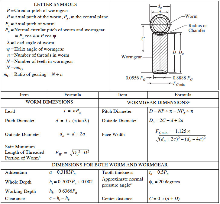
Equations for American Standard Fine Pitch Worms and Wormgears Per. The axial pitch of the worm and the circular pitch of the gear must be same for a mating worm and gear. Worm lead angle ie.
Mm so try m 2. A self-locking worm and wheel gear set can only be driven forward by rotation of the worm. Gears Engineering and Design.
I are practical and have applications that are very successful. View Design of Worm Gearpdf from ME MISC at VIT University Vellore. M 2 gives a face width less than the catalog value of 25 mm so OK.
αW λ 90. View Worm Gear Design Procedurepdf from ME ME481 at University of San Jose - Recoletos Basak Cebu Campus. A high-efficiency worm-gear speed reducer is desired to accept 20 hp.
By analyzing the spur gear slices for load and stresses the same can be obtained for the entire worm gear set. 1 19 Beam Strength of Bevel Gear Tooth 1 110 Worm and Worm Gears 1 11 1 Geometry and Velocity Ratio 1 112 Forces in Worm and Worm Gear 1 113 Designing of Worm Wheel 1 114. Flowchart for worm gear designing process.
We will use the term Pitch P for both the pitch in this tutorial. 158 Lin Tilley Rd. Transmitted Power Input and Output speed Center distance Type of.
Y38 037727 n 5594 rpm. Determination of contact pattern for double enveloping worm gear. The worm gear set.
P Circular pitch of wormgear P axial pitch of the worm P x in. It is common for worm gears to have reductions of 201 and even up to 3001 or greater Many worm gears have an. American Standard Design for Fine-pitch Worm Gearing ANSI B69-1977 This standard is intended as a design procedure for fine-pitch worms and wormgears having axes.
The worm is threaded screw and worm wheel is toothed gear. M 2 gives valu e for face. 32 Design Procedure for Selection of worm gears - Using PSG Design Data Book Manufactures Catalogue Step.
Thus it is usual to specify the lead angle. Power Transmission Problem Proposed solution. The worm wheel teeth envelope the treads on worm which gives line contact between mating parts.
Things should be made as simple as possible but no simpler This book is an attempt to apply that principle to gear. Design of Worm Gear.
Agma Worm And Spur Gear Design Equations And Calculators
Worm Gearing Classes Proportions Materials And Worm Gear Cutting

Pdf Design And Analysis Of Worm Pair Used In Self Locking System With Development Of Manual Clutch Esat Journals Academia Edu
Surface Durability Of Worm Gear Khk
Agma Worm And Spur Gear Design Equations And Calculators

Worm Gear Design Calculation Pdf Merge Peatix
Worm Gears Roy Mech

Basic Geometric Calculation For Worm Gears Inventor 2019 Autodesk Knowledge Network
0 comments
Post a Comment